!! Important note !!
No Motobike Manufactor have had involvement in this product.
The use of a manufactures name and / or model designation to describe
the motorcycles on this site does not imply that the manufacturer endorses
the use of this application.
No Motobike Manufactor have had involvement in this product.
The use of a manufactures name and / or model designation to describe
the motorcycles on this site does not imply that the manufacturer endorses
the use of this application.
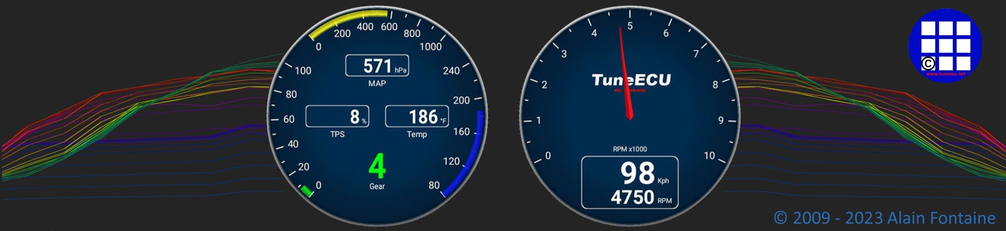
Engine Management System Information
Jump to: - Sensors Actuators
.
System
Description (Speed
Triple 1050)
.
.
Goto Speed
Triple T509 (885 cc) & 955cc
Goto
Goto
Daytona 675
Goto Rocket
III
.
The Speed Triple is fitted with an electronic engine management system which encompasses control of both ignition andfuel delivery. The electronic control module (ECM) draws information from Sensors positioned around the engine, cooling
and air intake systems and precisely calculates ignition advance and fueling requirements for all engine speeds and loads.
In addition, the system has an on-board diagnostic function. This ensures that, should a malfunction occur in the engine
management system, the malfunction type, and engine data at the time the malfunction occurred, are stored in the ECM
memory. This stored data can then be recovered using a special service tool which is mandatory for all Triumph dealers.
In this way, precise diagnosis of a fault can be made and the fault quickly rectified.
System
Sensors
As
the density of the air (and therefore the amount of
oxygen available to ignite the fuel) changes with temperature, an
intake air temperature
sensor is fitted. Changes in air temperature (and therefore air
density) are
compensated for by adjusting the amount of fuel injected to a level
consistent
with clean combustion and low emissions.
Engine
coolant temperature sensor -
situated at the rear of the cylinder head, on the left hand side.
Coolant
temperature information, received by the ECM,
is used to optimise fueling at all engine temperatures and to calculate
hot and
cold start fueling requirements.
Throttle
position sensor
- situated
at the left end of the throttle body.
Used
to relay throttle position information to the ECM. Throttle opening
angle is used by the ECM to determine
fueling and ignition requirements for all throttle positions.
Barometric
pressure Sensor - situated on
the left hand side, at the front of the
rear mudguard beneath the seat.
The barometric pressure sensor measures atmospheric air pressure. With
this
information, the amount of fuel per injection is adjusted to suit the
prevailing conditions.
Manifold Absolute Pressure (MAP) sensor - situated to the left side of the airbox, connected to each of the three throttle bodies by equal length tubes.
The MAP sensor provides information to the ECM which is used at shallow throttle angles (very small throttle openings) to provide accurate engine load indications to the ECM. This degree of engine load accuracy allows the ECM to make very small adjustments to fuel and ignition which would otherwise not be possible from throttle angle data alone.
Road speed sensor - situated in the upper crankcase, on the left hand side, above the sprocket cover.
The road speed sensor provides the ECM with data from which road speed is calculated and displayed on the
speedometer. A vehicle speed limitation device also receives information from the road speed sensor.
The clutch must be pulled in for the starter motor to operate.
Crankshaft
position sensor
- situated in the crankcase, near the alternator
cover.
The crankshaft position sensor
detects
movement of a toothed wheel attached to the alternator rotor.
The toothed wheel gives a reference point from which
the actual crankshaft position is calculated.
The crankshaft position sensor information is used by the ECM to
determine engine
speed and crankshaft position in relation to the point where fuel is
injected
and ignition of the fuel occurs.
The lambda sensor constantly feeds information to the ECM on the
content of the
exhaust gases.
Side
stand switch - situated at
the top of the sidestand leg.
If the sidestand is in the down position, the engine will not run
unless the transmission
is in neutral.
System Actuators
In response
to signals received from the sensors, the
ECM controls and directs messages to a series of
electronic and electro-mechanical actuators. The
function and location of the actuators is given below.
The throttle
stepper actuates a cam/lever which causes variations in the closed
throttle
position. Although used primarily to ensure target idle speed is
maintained, it
also increases throttle opening when the engine is cold.
Canister
purge valve (California models only)- situated in
the vapour return line between the carbon
canister and
the throttle bodies. The purge valve controls the return of vapour
which has been stored in the carbon canister during the
period when the engine
is switched off. The valve is 'pulsed' by the ECM to give control over
the rate
at which the canister
is purged.
The spray pattern of the injectors is fixed but the length of
time each injector can remain Open is variable according to operating
conditions. The duration of
each injection is calculated by the ECM using data received frorn the
various sensors in the system.
There are three coils fitted, one for each spark plug.
The ECM controls the-point at which the coils are switched on and off.
In calculating
the switch-on time, the ECM allows sufficient time for the coils to
charge to a
level where a spark can be produced. The coils are switched off at the
point of
ignition, the timing of which is optimised for good engine performance.
The fall detection switch will detect if the motorcycle
is on its side and will cut power to the ECM immediately. This prevents
the engine from running
and the fuel pump from delivering fuel. In the event of a fall, the
switch is reset by returning
the bike to an upright position and switching the ignition off then
back on again.
Main
power relay - situated
under the seat.
When the ignition is switched On, the main power relay
is powered up to provide a stable voltage supply for the ECM.
Fuel
pump - located
inside the fuel tank.
The electric pump delivers fuel into the fuel system, via
a pressure regulator, at a constant 3 bar pressure.
The pump is run continuously when the engine
is operating and is also run briefly when the ignition is first
switched on to ensure that 3 bar is
available to the system as soon as the engine is cranked. Fuel pressure
is controlled by
a regulator also situated inside the fuel tank.
Cooling
fan - located
behind the radiator.
The ECM controls switching on and off of the cooling fan
in response to a signal received from the coolant temperature sensor.
When the coolant temperature
rises to a level where the cooling effect of natural airflow is
insufficient, the cooling
fan is turned on by the ECM. When the coolant temperature falls
sufficiently, the ECM turns the cooling
fan off. The fan only becomes operational when the engine is running.
It will not
operate at any other time.
Secondary
air injection
solenoid - located in front of the
airbox.
The secondary air injection solenoid controls airflow
through the secondary air injection system.
In this
system, the starter lockout system (clutch
switch, neutral switch,
sidestand
switch) all operate through the engine management ECM.
!! Important note !!
No Motobike Manufactor have had involvement in this product.
The use of a manufactures name and / or model designation to describe
the motorcycles on this site does not imply that the manufacturer endorses
the use of this application.